Search Results
93 results found with an empty search
- Upgrading to PA-12S: What You Need to Know
At Tempus 3D, we’re always looking for ways to improve the quality, consistency, and performance of the parts we produce. That’s why we’ve made the decision to switch all of our in-house Multi Jet Fusion (MJF) production from PA-12 to PA-12S. While PA-12S may sound like a small variation, it introduces a number of subtle improvements that benefit both the printing process and the final part quality. What Is PA-12S? PA-12S is HP’s next-generation nylon 12 material for MJF 3D printing. Like the standard PA-12 you may already be familiar with, PA-12S is a strong, durable thermoplastic known for its excellent mechanical properties, dimensional stability, and chemical resistance. It keeps everything that made PA-12 a reliable material and introduces a few refinements that make it better suited for high-quality, high-consistency manufacturing. Key Benefits of PA-12S 1. Smoother Surface Finish Thanks to a more refined particle structure, PA-12S produces parts with a PA 12 S is ideal for producing premium surface aesthetics noticeably smoother surface straight out of the printer. This improves part quality and can reduce the amount of time needed for post-processing, sanding, or finishing. 2. Greater Consistency in Builds One of the biggest benefits of PA-12S is improved print consistency across different part geometries, sizes, and orientations. This makes it easier for us to maintain tight tolerances and deliver predictable results, even in complex or high-detail projects. 3. Improved Flow and Packing Efficiency PA-12S has better flow characteristics during the powder spreading process, which helps reduce variability from build to build. This also enables more efficient packing of parts in each print job, which helps us reduce lead times and increase throughput. 4. Strong and Functional Parts Like standard PA-12, PA-12S offers excellent mechanical strength and durability. It remains a great choice for both prototypes and production parts that need to handle wear, load, and repeated use. The material is still well suited for functional applications across industries like automotive, medical, robotics, and consumer products. 5. Great Material Refresh Rate PA-12S retains a similar material refresh rate as PA-12, this keeps our production just as efficient and sustainable as before, while offering improvements in print quality. Applications That Benefit Most from PA-12S While PA-12S is a strong all-around material, but it especially shines in the following applications: Mechanical parts that require tight tolerances Snap fits and enclosures that need dimensional stability Production components with repetitive geometries or large print volumes Prototypes that need a good balance of strength, accuracy, and speed Parts with fine features where surface smoothness adds value If your application previously used PA-12, the transition to PA-12S will feel seamless, but the results may be more consistent and visually cleaner. No Need to Change Your Files The best part is that this upgrade requires no changes on your end! We will be transitioning to PA-12S for all MJF prints, so every new part you order will soon benefit from these improvements automatically. If you’ve ordered parts from us before using PA-12, you can expect the same great performance, with a few improvements that may reduce finishing time and improve overall part consistency. ____________________________________________________________________________________________ Tempus 3D is an HP certified 3D printing service bureau based in British Columbia, Canada, offering advanced additive manufacturing solutions tailored to your production needs. We specialize in HP MJF, Sinterit SLS, and Formlabs SLA technologies. Have a project in mind? Contact us at info@tempus3d.com to learn how we can support your next build. Let’s make it possible!
- Monthly News Letter: Canadian 3D printing company, Tempus 3D receives $250k recycling program grant!
From left to right. Robert Tempus 3D CEO, Jordon Production Manager, Jonathan Manufacturing Advisor
- SLS vs MJF 3D Printing: What’s the Difference and Which One Should You Choose?
If you’re looking to print strong, functional plastic parts, two of the most popular industrial 3D printing technologies are SLS (Selective Laser Sintering) and MJF (Multi Jet Fusion). At a glance, they might look similar. Both are powder bed fusion processes and often use the same materials like Nylon PA 12. But under the surface, they work in different ways. Those differences can have a big impact on print speed, surface finish, material options, and overall part performance. Let’s take a closer look. How Are They Similar? Both SLS and MJF use a powder-bed fusion process. A thin layer of powder is spread across the print bed, and only the areas that make up the part are fused. The surrounding powder remains loose, providing natural support during printing. This approach offers several key advantages over more traditional 3D printing methods like FDM (Fused Deposition Modeling): No support structures required Excellent for complex geometries, including internal channels and overhangs High level of detail and resolution Efficient for batch production, with many parts printed at once in a single build The main difference between the two lies in how they fuse the powder! Sinterit Lisa X (Left) representing an SLS machine, HP MJF 5200 (Right) showing a Multi-Jet Fusion machine SLS: Selective Laser Sintering SLS is a well-established technology that uses a high-powered laser to scan and fuse powder particles layer by layer. After each layer is complete, the machine spreads a new layer of powder and continues building the part from the bottom up. Strengths of SLS: Handles complex geometries and internal features with ease Compatible with a wide variety of materials, including flexible nylons and composites Proven technology with a long track record in both prototyping and production No support structures needed, allowing efficient use of build volume MJF: Multi Jet Fusion MJF, developed by HP, uses inkjet-style heads to deposit fusing and detailing agents onto the powder bed. After these agents are applied, an infrared heating element passes over the surface to fuse the entire layer at once. This simultaneous layer fusion makes MJF notably faster than SLS in many applications. It also results in stronger and more consistent parts, especially in the Z-axis. Strengths of MJF: Also excels at complex geometries and fine features Faster build times, especially for large batch runs High part-to-part consistency within and across builds Smooth surface finishes and sharp detail resolution High powder reuse rate, which reduces material waste and production cost Improved Z-axis strength, with more uniform mechanical properties in all directions Which One Should You Choose? Both technologies can produce strong, high-quality nylon parts suitable for real-world use. The better choice depends on your specific application and priorities. Best For SLS MJF Small to medium batches Yes Yes High-detail, high-volume production Slower Faster and more consistent Flexible or specialty materials More options More limited Smooth surface finish and crisp edges Good Excellent Cost efficiency at scale Moderate powder reuse Higher powder reuse Complex geometries Yes Yes Strong Z-axis properties Moderate Excellent In short: Choose SLS if you're working with flexible or composite materials, or need a broader material selection for functional prototyping. Choose MJF if you want fast turnaround, smoother finishes, and strong, consistent mechanical properties in every direction, especially for production parts that will be under load. Not Sure Which One to Use? Choosing the right technology often comes down to your specific part geometry, surface finish requirements, timeline, and budget. If you're not sure which one fits your needs best, we’re happy to help. Send us your part files or reach out with your project goals. We’ll recommend the best process to get the job done right. Tempus3D is an HP certified 3D printing service bureau based in British Columbia, Canada, offering advanced additive manufacturing solutions tailored to your production needs. As one of Canada's most capable additive manufacturing service bureaus we proudly serve customers from coast to coast. Specializing in HP MJF, Sinterit SLS, and Formlabs SLA technologies. Have a project in mind? Contact us at info@tempus3d.com to learn how we can support your next build. Let’s make it possible!
- Brace Yourself: How Cascade Orthotics Uses 3D Printing to Transform Patient Care
Cascade Orthotics Designed 3D Printed Back Brace Multi-Jet Fusion PA-12 Nylon Hand brace For over 30 years, Cascade Orthotics has been a trusted name in custom orthotic care in Calgary. Best known for their work in spinal orthotics, they've continued to grow and adapt by expanding their services and embracing the latest technologies. We caught up with Jeff Wright to hear more about Cascade’s journey, their day-to-day work, and how they’re using modern tools to make a real impact on patients' lives. Be sure to check Cascade's website! Instagram: @cascadeyyc Getting Started and What Drives Them Can you tell us a bit about how Cascade Orthotics got started and what made you want to get into this kind of work? The business has been around for about 30 years. I’d say Cascade is most known for providing spinal orthotic care. We deal with a lot of trauma related to spine fractures and scoliosis. Even though we do a lot of other types of orthotics and bracing, that’s probably what we’re most known for. Personally, I was drawn to the field because it brings together a lot of different disciplines. I liked the idea of applying anatomy, materials science, and biomechanics. I also enjoy working with advanced technology like 3D scanning and CAD, and being able to use that to help people. How have things changed at Cascade since it first opened? In the ten years I’ve been involved, we’ve definitely broadened what we do. While we still do a lot of trauma spinal work, we now provide a wider range of orthotic services. We also work with a bigger variety of patients, from kids to seniors. What values or goals guide your team in how you treat patients? We really focus on offering a modern approach to orthotic care. Our team considers ourselves early adopters of 3D scanning, CAD design, and digital fabrication tools like carving and 3D printing. Services and Patient Care You offer a wide range of orthotics. What kinds of conditions do you usually treat? I like to describe it as head-to-toe bracing. I always joke that we do everything except teeth, since people often mix us up with orthodontists when we say we’re orthotists. Some of the most common conditions we see include stroke, spinal cord injury, multiple sclerosis, spina bifida, arthritis, and traumatic fractures. How do you make sure each device is really tailored to the individual? Most of what we do is custom-made. The design process is a mix of clinical experience, patient feedback, and knowledge of what’s considered best practice for the specific type of orthosis that’s needed. Do you work with other healthcare providers as part of your care process? Yes, quite regularly. Orthoses are typically prescribed by general physicians or specialists. Many of the people we work with also see physiotherapists or occupational therapists. When we’re working with inpatients, we rely a lot on nurses and hospital staff too. Tools and Technology You’ve mentioned using things like 3D scanning and printing. How have those changed the way you work? We rely heavily on digital workflows for a few key reasons. For one, they allow us to be more efficient. We don’t need to deal with heavy plaster casts, which is especially helpful when working with torsos or large limbs. It also saves us from a lot of the hands-on manual work like casting, filling casts, and modifying by hand. We also find the digital tools are also more accurate. Our 3D scanners have a high degree of precision, and CAD software helps us make very exact design adjustments. Then with 3D carving and printing, we’re able to fabricate devices that really maintain that accuracy all the way from scan to final product. 3D printing in particular has been a big step forward. It gives us design flexibility that we don’t have with traditional vacuum forming. That means we can make devices that look and perform differently. What do you like about using PA-12 nylon in your devices? We like PA-12 and the MJF process because of how consistent and strong it is. It has a high level of isotropy, which is important for durability. We can drill into it, attach components with rivets, and even make some adjustments after it’s been printed. Working with Patients What do you do to make sure your patients have a good experience? We always try to understand what their goals and expectations are. Then we match that with our own knowledge and experience to come up with a solution that we’re all confident in. Whenever possible, we like to give patients a few different options and let them decide which direction to take. How do you gather feedback and use it to improve? That’s something we’ve started focusing on more recently. We just launched our social media platforms to help share more about what we do and also to encourage patients to show us what they’re doing with their orthoses. We’re also launching a formal feedback program within the clinic. Looking Ahead You’re based in Calgary. Do you do much community outreach or public education? That’s something we’re hoping to build on through our social media presence. We want to raise awareness about orthotic care. We also provide in-service or education sessions to different hospital units to increase their knowledge about working with orthotic inpatients. What’s next for Cascade Orthotics? Are there any new tools or services you’re excited about? We’re always keeping an eye out for new products and technology. Right now, we’re interested in adding a degree of automation to our workflow in order to make our design process even more efficient. We also think that could help us grow our 3D printing capabilities. How do you stay on top of what’s new in the orthotics field? Our clinicians attend different conferences focused on orthotic care. We also meet with product reps who keep us up to date with new materials and components. And, we talk with our colleagues in the field to learn what’s working for them. We love proudly supporting forward-thinking clinics like Cascade Orthotics with precise, production-grade additive manufacturing. Multi Jet Fusion 3D printed Foot and Ankle orthodic Tempus 3D is an HP certified 3D printing service bureau based in British Columbia, Canada, offering advanced additive manufacturing solutions tailored to your production needs. We specialize in HP MJF, Sinterit SLS, and Formlabs SLA technologies. Have a project in mind? Contact us at info@tempus3d.com to learn how we can support your next build. Let’s make it possible!
- Student Case Study: Umbrella's Handle Case Study
By Raul: Selkirk College Student of the Digital Fabrication a Design program. Umbrella with 3D printed handle Almost 2 years ago, I bought a new umbrella which was neat as it opened the other way, opposite to the traditional ones. However, it came with a cheap and hollow handle, which I took on as a personal project because I wanted to design my own custom handle. I started this project while I was living in Vancouver, where rain is a constant element you face in daily life. However, as I no longer live there, I thought it would be a perfect Christmas present for my sister, who does. I decided to scan and repair this project because I found it was the perfect example to show and test how a custom design can be adapted into a commercially generic design and use additive manufacturing to create the new piece. The way I addressed this problem was by getting rid of the previous handle. Then, I used one wooden dowel as a shaft, wrapped it with clay, and had a female friend of mine wrap her hand around it and use it as a template. As this is intended to be a present for my sister, and hand ergonomics vary a lot between a man’s and a woman’s, her help was of great use. 3D Scanning of physical prototype of umbrella handle Once the clay dried and solidified, I scanned the rough shape of the clay handle to get a mesh and start working on my design. I imported the obtained mesh into VX Elements, which helped me a lot to clean up the mesh, shape it with organic curves, and then export it into Fusion 360. The next step I did was to convert it from a mesh into a solid body, where I sculpted some features into the handle such as the inner shaft diameter and its depth. Once I obtained the mesh and edited it in Fusion, I started making modifications between Fusion and VX Elements, which provided me with different results that were getting closer to the desired grip, with the shape of the fingers I wanted and aiming to create organic shapes. Umbrella with 3D printed handle Once I obtained the final piece that I was satisfied with, I engraved my sister's initials on the bottom. I also designed a hole to attach a string to secure the umbrella. Once it was ready, I mounted it on the umbrella to check if the design provided the desired height. Once I confirmed the size was correct, I sent my design to Tempus 3D to bring it to life. I am thrilled with the result! Now, all that is left is to take it to Vancouver and give it to my sister as her Christmas gift. What would I do differently next time? I think next time I would mount the clay on the umbrella from the very beginning to better calculate the dimensions, both the thickness of the piece and the height at which it should be placed. It was a very intuitive process, where each refinement and 3D print of each iteration provided quite different results, so it took many trials to reach the outcome. I also think I would focus more on aesthetic design, as it now serves a functional purpose by adding extra weight to act as a counterbalance, but I feel I need to work on the proportion design. One thing I consider a success is that, since it is a large and solid handle, its weight helps counterbalance and stabilize the weight of the umbrella itself. I believe the final client will have the last word, so it will be important to listen to her feedback, as this is a complete surprise, and the entire design has been based on estimates of her hand proportions and height. Umbrella with 3D printed handle Handle Prototype Clay Model of umbrella handle Umbrella before modification Umbrella before modification Tempus3D is an HP certified 3D printing service bureau based in British Columbia, Canada, offering advanced additive manufacturing solutions tailored to your production needs. We specialize in HP MJF, Sinterit SLS, and Formlabs SLA technologies. Have a project in mind? Contact us at info@tempus3d.com to learn how we can support your next build. Let’s make it possible!
- How Canadian 3D Printing Is Reshaping Manufacturing and Beating Supply Chain Woes
Remember when it felt like the world ran out of everything from toilet paper to auto parts? Global supply chain disruptions made headlines for years, but quietly, a powerful solution has been emerging: 3D printing. Why 3D Printing Is a Game-Changer Industrial 3D printing enables objects to be built layer by layer from digital blueprints. It’s like having a fully functional mini-factory right where you need it, no more waiting weeks for overseas shipments or navigating customs delays. Local Manufacturing, Global Advantages The impact of 3D printing, especially 3D printing in Canada, is profound: - Production Where It’s Needed: Whether it’s Toronto, Vancouver, or a remote town in the Yukon, industrial 3D printers can set up shop close to end users. Need a replacement part? Just print it locally. No transcontinental shipping required. - Faster Prototyping and Personalization: Businesses can design, prototype, and refine products within days and often without leaving the country. - Reduced Waste and Inventory: The “print-on-demand” model means fewer resources are wasted, and less capital is tied up in unused inventory. Beating the Supply Chain Bottleneck Traditional supply chains falter when overseas factories shut down or shipping routes are clogged. Made-in-Canada 3D printing solutions offer a nimble alternative: - Streamlined Production: Skip the middlemen. Designs go straight to production, minimizing error points and delays. - Rapid Response Capability: Need an urgent part replacement? Local industrial 3D printing facilities can deliver within hours. - Supply Chain Resilience: Localized production reduces dependence on fragile global networks. Whether it’s a pandemic or port shutdown, communities stay operational and secure. The Future Is Local and Layered Gone are the days when 3D printing was only for hobbyists and engineers. Today, it’s fueling a quiet revolution in how we make things—more flexibly, more sustainably, and more locally. 3D printing in Canada is leading the charge, empowering businesses and communities to design and produce faster, cleaner, and smarter. Ready to explore the benefits of industrial 3D printing for your business? The next revolution in manufacturing is already underway. Tempus 3D is an HP certified 3D printing service bureau based in British Columbia, Canada, offering advanced additive manufacturing solutions tailored to your production needs. We specialize in HP MJF, Sinterit SLS, and Formlabs SLA technologies. Have a project in mind? Contact us at info@tempus3d.com to learn how we can support your next build. Let’s make it possible!
- Future Innovators in Action! 5 Student Projects Powered by 3D Printing at Tempus 3D
At Selkirk College’s Digital Fabrication and Design program, innovation meets real-world problem solving—one layer at a time. With the support of Tempus 3D’s industrial 3D printing services, students recently brought their creative visions to life by reverse engineering broken or outdated parts and replacing them with customized, functional solutions. Here's how they did it: Danielle tackled a frustrating BBQ wheel that wouldn’t stay in place. Her redesigned part was stronger, more stable, and made to last using 3D scanning and modelling. Read here! Jace solved an everyday gamer problem by creating custom Xbox controller battery covers that fit oversized rechargeable packs—no more cracked plastic or battery swaps gone wrong. Read Here! Jordon redesigned a pull saw handle for a better grip, easier blade changes, and longer life. His MJF-printed nylon part combined traditional Japanese styling with modern 3D printing precision. Read Here! Yan rescued a broken ski boot buckle using high-performance PA-12 material and Multi Jet Fusion technology, proving that even small parts can have a big impact. Read Here! Matt repaired a windshield wiper bracket after winter weather had made the original plastic brittle and unusable. Instead of buying an entirely new wiper assembly, he reverse engineered the broken part, reinforced the design, and used MJF nylon to create a precise, durable replacement ready to handle snow, UV rays, and washer fluid. Read Here! Raul explores the design and 3D printing of a custom umbrella handle, created as a thoughtful and functional gift. By combining clay modeling, 3D scanning, and digital design tools, the project demonstrates how additive manufacturing can transform a personal idea into a tangible, ergonomic product. Read Here! These projects are more than class assignments—they’re proof that 3D printing for custom parts is changing the way we repair, prototype, and design. Whether it’s reverse engineering, product improvement, or creating something totally new, these students used cutting-edge tools to make meaningful change. We love supporting each student helping to bring their ideas to life and build real-world skills in advanced manufacturing. We're proud to support the next generation of creators. Tempus 3D is an HP certified 3D printing service bureau based in British Columbia, Canada, offering advanced additive manufacturing solutions tailored to your production needs. We specialize in HP MJF, Sinterit SLS, and Formlabs SLA technologies. Have a project in mind? Contact us at info@tempus3d.com to learn how we can support your next build. Let’s make it possible!
- Student Case Study: 3D printed saw handle.
By Jordon: Selkirk College Student of the Digital Fabrication a Design program. 3D printed saw blade handles The Client, Bruce, had his pull saw break during use, the original part was an injection moulded saw handle with a push button blade release, the two halves of the saw handle were held together with only 2 plastic pins leading to the failure of the part. Bruce wanted a stronger part with a simpler blade attachment method. He asked for a customized grip inspired by Japanese wrapped bamboo handles. Bruce also commented on the original’s nail hole being too small to hang the saw when not in use. We chose to 3D scan the part and reverse engineer the design. The part was printed in MJF nylon PA12 to allow for internal voids to reduce material needed while allowing the part to be made in one piece to add to the strength of the part. MJF technology was chosen over the original injection moulding to allow for more complex geometry and reduce waste, along with the cost difference for custom one-off parts. To further reduce waste, prototyping was done in FDM PLA to ensure that everything would fit in the final part. FDM was not chosen to be the final technology because of layer adhesion and support issues. Showing the first 3D printed prototypes Nylon was chosen over the other materials for the lower cost and higher flexibility to reduce the chance of cracking in the future, 3D printing allowed for part personalization with out making custom injection moulds. The part was printed hollow with 5mm wall thickness to balance strength and weight. Finished 3D printed handle up close Bruce was happy with the results of the repair and the feel and quality of dye used on the nylon. My design was not completely optimized for MJF printing, I had some semi-blind holes that trapped powder and made it difficult to clean and dye evenly. The nylon did offer greater strength and flexibility as expected and should result in a long lasting custom tool that can be handed down for generations. 3D scanning model of the original broken saw handle 3D scanning model of the original broken saw handle Original saw handle fitment Finished Multi-Jet Fusion 3D printed saw blade handle Finished Multi-Jet Fusion 3D printed saw blade handle Tempus 3D is an HP certified 3D printing service bureau based in British Columbia, Canada, offering advanced additive manufacturing solutions tailored to your production needs. We specialize in HP MJF, Sinterit SLS, and Formlabs SLA technologies. Have a project in mind? Contact us at info@tempus3d.com to learn how we can support your next build. Let’s make it possible!
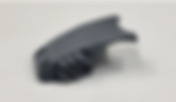
- Student Case Study: Barbecue Foot With Attached Wheel
By Danielle: Selkirk College Student of the Digital Fabrication a Design program. Original and Multi-Jet Fusion 3D printed replacement part The part that I have for our Scan Improve Repair Tempus Case Study is a BBQ foot with a wheel attached. I received this part from one of our instructors, Kailey. She had a friend with a broken part that needed fixing. It was a BBQ foot with a wheel attached. The foot part that attaches the wheel to the leg is the part that needs to be fixed. It would fall off the leg of the barbecue constantly. It would work better and be more stable if it had more support within the structure of the part. It would make it stronger and stay in place every time the client needed to move the unit to use it, clean it or store it away. Original and Multi-Jet Fusion 3D printed replacement part The client found it quite a headache every time they would want to use the BBQ and needed to move it. Fixing the part will relieve that stress of the BBQ falling when moving and someone potentially getting hurt. Fixing the part will also help it not fall and damage other parts of the unit. I ask myself, when I am thinking of a new design or a part that needs enhancements. Things to think about when coming up with solutions for the BBQ foot would be: What is it lacking? Why does this part continue to fail with its intended purpose? The Scan Improve and Repair process was straightforward with this part. The intention of fixing this part is to make it better, stronger, and more durable without falling off, having the unit fail, damaging property, or falling and hurting someone. Shawn, Kailey and I had a discussion on what the part needed and what was going to be the best way to achieve success with this part. We talked about filament, what to extrude if any, maybe thickening the wall with more filament and deeper extrusions along with deeper indents all the way around. We need the to be careful not to change the structure of the part in its original state too much, otherwise, the BBQ leg will not fit will not with the modified part. These are my solutions or recommendations that I must fix this barbecue leg part with the attached wheel. These improvements would be to make this part stronger and with better structure by extruding extra filament to make it tighter, adding to the previous extruded parts. I would do the same with indented parts as well. When the BBQ leg slides inside the leg, it should be stronger and more durable. The steps that I would take to implement a solution for this problem would be starting with scanning the part with a a3D scanner. Many points as I can. Around the outer area and the threats inside. Collecting as much detail as you can is the most important to save for more work later. After the scanning process is done, then I would upload that into VX Elements to create a mesh. Create a mesh and fix the mesh. Fix the holes, make sure it's solid. Then export that out of the VX Elements. Once that is completed it is then uploaded into Fusion 360 to sketch out the part using the mesh you just created. Sketch and then turning that into a 3D model from there. I would export that out of Fusion into an STl file and have it 3D printed. I would make sure that I check the thread count. Measure the bolt size and length and figure out the pitch. For the bottom of the leg in the fusion file, I would make sure that all the extrusions are still a little bit further out to give them more support. Extend them a bit further then the original and fillet it the edges to keep it neat. This will give the part more stability without changing the structure of it too much. Some of the challenges might be not being able to see and capture all the targets. It such an important step to scan properly to be able to get as much information as we can to make that mesh to be able to close it and turn it into a proper file that the 3-D printer can read the thread. Count could be off, measure properly. If the extrusions are not the right dimension. When the leg is put over top of this foot, it'll slip down because the extrusion won't be there to catch it. If I were to do this part again, I would probably do it the same. I like the way this part and the mesh came together very well. The scan was really great detail. We got a lot of information from it. So, it imported into the and then VX Elements, then into Fusion quite well. It was a pretty quick part. Design and create makes changes and implement them to seeing and problems. I think this part was a success. I will hear from the clients. Tempus 3D is an HP certified 3D printing service bureau based in British Columbia, Canada, offering advanced additive manufacturing solutions tailored to your production needs. We specialize in HP MJF, Sinterit SLS, and Formlabs SLA technologies. Have a project in mind? Contact us at info@tempus3d.com to learn how we can support your next build. Let’s make it possible!
- Student Case Study: Windshield Wiper Bracket Repair
By Matt: Selkirk College Student of the Digital Fabrication a Design program. Challenge: While taking the windshield wiper blades off at the end of winter, part of the plastic tab broke off leaving the part and wiper blade inoperable. Through a winter of extreme cold weather and snow , combined with washer fluid and UV rays the plastic became brittle. The part broke from the stress of removing it. This part is the cover for the main anchor and pivot point between the “wiper arm” and “wiper blade.” With this broken there is no structural integrity holing the two parts together. Multi-Jet Fusion PA-12 3D printed replacement part for windshield wiper Multi-Jet Fusion PA-12 3D printed replacement part for windshield wiper Options for Solutions: In the past there were limited options to solve this problem. 1. The first option would be to glue the parts back together. Pros - Quick, Simple and Cheap Cons - Broken tab might be lost. Unlikely to hold up against the wear and tear 2. Buy a replacement part. Pros - The replacement part would be brand new and a direct replacement Cons - Ordering a new part involves buying the whole wiper blade. This is roughly a $70 item and is excessive and wasteful considering such a small part is needed. - The new part is just as likely to break in the same spot again in the future. Solution or recommendation: The solution to fix this problem was to scan the broken object and edit the part to restore it to it original design. In doing this it is also possible to reinforce the part in the areas that it is showing weakness. This was done by adding some extra material and changing the shape slightly to reduce stress concentration point. With the file complete traditional FDM was used. Fine details and the complexity of the part did not allow for this to be a high quality option. The high print quality and detail of the Nylon MJF method made it the perfect candidate for this object. 3D scan of original windshield part There were several steps involved in implementing this solution: • Scan the broken object. • The scanned model was edited using VX Elements. This software allowed me to clean up the broken area and mirror the good side. Creating a new symmetrical object. • The model was then cleaned up and smoothed out to remove any imperfections. Critical areas were reinforced to make them more robust. Some of the other contact areas were cleaned to make sure the new part fit true to the original. • Once the model was completed the file was sent to the HP Nylon MJF printer and a new part was made. The biggest challenge was getting the tight tolerances of the contact point to fit. The part does fit and do it’s intended job but there are a few little areas that could be modified slightly to help the part fit perfectly. The repair of the windshield wiper bracket was a success! The test now will be to see how the material will hold up to the Snow, UV and washer fluid of a winter season. Multi-Jet Fusion PA-12 3D printed replacement part for windshield wiper Tempus 3D is an HP certified 3D printing service bureau based in British Columbia, Canada, offering advanced additive manufacturing solutions tailored to your production needs. We specialize in HP MJF, Sinterit SLS, and Formlabs SLA technologies. Have a project in mind? Contact us at info@tempus3d.com to learn how we can support your next build. Let’s make it possible!
- Student Case Study: Reverse Engineering + Additive Manufacturing with HP MJF: Ski Boot Buckle
By Yan: Selkirk College Student of the Digital Fabrication a Design program. CAD Model of 3D scanned and repaired ski boot buckle The Problem: A Broken Ski Boot Buckle The part I am working on is from my instructor Shawn, which he received from a repairing business during his visit to KORE summit in Kimberly. It’s a part for footwear according to him, for description purposes in this report, I named it the Ski Boot Buckle. The buckle is an injected plastic part, with an overall dimension of 35´22mm, average thickness of 1.25mm. Without having the radius on edges measured, I observed larger radius added, making the part thinner. It also looks thinner at the junction of edges, where the failure happened, as shown in photo above, I put a staple to open it wider to easily illustrate it. Failure of this tiny part will result the whole boot to be completely useless, as the user can hardly get it to buy separately. Original broken ski boot buckle to be 3D scanned Options for solutions are: # Options Pros Cons 1 Replace with the same part from used boot. • same dimension • same material • with tear and wear • same weakness 2 Replace with a similar part available • may work, saving the boot from completely wasted • compatible, but not perfectly match 3 Replace with a 3D printed part • Reverse engineerable • Same dimension • Optimized structure. • Optimized material. • Saving the whole boot. • Repeatably printable digital file. • More improvement if the printed part fails. — Options for 3D printing materials available: # Material Property 1 PLA • Brittle and prone to cracking or snapping under load • Poor impact resistance • Low flexibility 2 PETG • High impact resistance • Moderate flexibility 3 PA-12 • Very high impact resistance • High flexibility Options for printing methods available: # Material Method Advantages 1 PLA FDM • Have layer lines, prone to delamination. • Strength depending on layer orientation. • Less durable, may fail under extended use. 2 PETG FDM — 3 PA-12 MJF • No support structure, powder supports parts. • High durability and fatigue resistance. With all options compared, the superior solution is to replace the broken buckle with one that is using HP MJF 3D printed, the final parts are shown as: Multi-Jet Fusion (MJF) 3D printed ski boot buckle Multi-Jet Fusion (MJF) 3D printed ski boot buckle Multi-Jet Fusion (MJF) 3D printed ski boot buckle When I received the final printout, I compared it with the original part again by bending it, the original part is brittle and cracked like PS (polystyrene), while the print out has smooth finish requires no further post-processing, it has properties of impact and fatigue resistance that is right for the buckle. The biggest challenge for me was to align the scanned model in VXelements, to create planes and cross sections, and subsequently to transfer the cross sections to fusion as sketches. It was a successful assignment, though the final model surfaces are not parallel, give me an angle of 0.033 deg, as shown in photo: CAD model of 3D scanned and repaired ski boot buckle What I would do to improve is to get more skillful with the scanning process, mesh editing and surfacing in VXelements. Steps in achieving this part shown as: Tempus 3D is an HP certified 3D printing service bureau based in British Columbia, Canada, offering advanced additive manufacturing solutions tailored to your production needs. We specialize in HP MJF, Sinterit SLS, and Formlabs SLA technologies. Have a project in mind? Contact us at info@tempus3d.com to learn how we can support your next build. Let’s make it possible!
- Student Case Study: Solving the Xbox One Controller Battery Cover Issue
By Jace: Selkirk College Student of the Digital Fabrication a Design program. Challenge: When I switched to rechargeable battery packs for my Xbox One controller, I noticed they were slightly larger than regular AA batteries. This made the battery cover either get stuck or put a lot of strain on it. Changing the batteries became a hassle, and I started worrying that I might end up damaging the covers. I was especially concerned that constantly forcing the cover on and off could eventually cause the plastic to crack or warp, shortening the lifespan of the battery covers Xbox battery cover and batteries Solution Options: 1. Buy Rechargeable AAs instead: Rechargeable AA batteries ○ Pros: Purchasing a set of rechargeable AA batteries would resolve the issue of the battery cover fitting properly. There would be no need for modifications or other changes. ○ Cons: The primary downside was that this solution would render my current rechargeable battery packs obsolete. Buying new battery packs would also be an additional cost 2. Make Custom Battery Covers: 3D scanned and repaired CAD model ○ Pros: This would involve designing a custom cover that would provide the necessary space for the slightly larger rechargeable battery pack. The benefit of this option was that I could solve the issue without replacing the battery packs themselves. A custom design would ensure the cover fits snugly without stress. ○ Cons: The difficulty with this solution is the complexity of reverse-engineering the cover. It would require accurate measurements, which could be time-consuming and technically challenging 3. Use No Battery Covers: Original and Multi-Jet Fusion (MJF) 3D printed battery cover ○ Pros: Removing the battery cover entirely would allow for an easy solution, as there would be no constraints on the battery size. It’s a free and quick fix with no need for further modifications. ○ Cons: The main downside was the exposed batteries. Without a cover, the batteries could easily become dislodged. Additionally, I would risk losing the battery covers over time 4. Force Battery Covers on: Original xbox battery cover ○ Pros: This would allow the existing battery cover to remain in use, ensuring that the protection for the batteries remains. The cover would stay intact, and the batteries would remain secured. ○ Cons: Forcing the cover onto the controller could cause damage, It would also make swapping the battery packs more difficult and cumbersome. Solution Chosen: I decided to proceed with the solution of making custom battery covers. This solution was ideal because it addressed the issue directly without requiring the purchase of new battery packs. Additionally, reverse engineering is fun and the availability of a 3D scanner and Tempus’s printer provided through the DFAB program made this solution practical. Result: The process of creating the custom battery covers began with scanning the original controller case. I used the 3D scanner to get a very close model of the existing battery cover. After gathering the scan data, I took measurements from the battery cover to refine the model. Next, I modified the 3D model to accommodate the slightly larger rechargeable battery pack. Xbox controller with 3D scanned and MJF Multi-Jet Fusion 3D printed replacement battery cover This required adjusting the depth of the compartment where the battery pack would sit, providing the necessary extra space. The only issue encountered was incorrectly estimating the corner radius, which I fixed in my next test. In the future, If I didn't have access to a 3D scanner or the necessary tools for creating a custom cover, I would likely opt for rechargeable AA batteries instead, as they would fit into the existing cover and avoid work with other devices. However, reverse engineering is fun. Overall, the solution was a success. The custom covers provided the additional space needed for the rechargeable battery pack. The stress on the cover was eliminated, and I didn’t experience any issues with forced fit or damage to the covers. Tempus 3D is an HP certified 3D printing service bureau based in British Columbia, Canada, offering advanced additive manufacturing solutions tailored to your production needs. We specialize in HP MJF, Sinterit SLS, and Formlabs SLA technologies. Have a project in mind? Contact us at info@tempus3d.com to learn how we can support your next build. Let’s make it possible!